 |
|
|
Datasheet as PDF
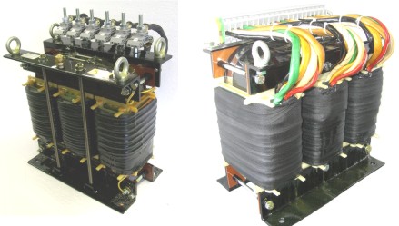
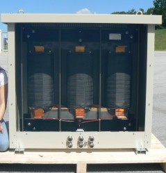
Three-phase line reactors with soft magnetic cut cores for power application conform to VDE 0570 / EN 61558
|
|
    
|
|
|
|
|
BV 2983044/045/046 and BV 32016002
|
|
|
Fields of application
|
|
|
Line reactor, commutation reactor, PFC reactor, armature-circuit choke, intermediate circuit choke (direct link inductor), boost converter
|
|
|
Description
|
|
|
The size is determined by the energy E = 0,5 x L x I². All given values are calculated for low warming and low humming. With forced cooling smaller dimensions are possible. If there is only a bit of over temperature allowed, the dimensions will increase.
Chokes for one-phase consumers and electronic devices with the following advantages:
Use as a smoothing reactor or commutation reactor in DC circuits
- low ripple factor
- attenuation of current harmonics
- bridging of line failures
- limitation of current peaks
Use as line reactor
- attenuation of current harmonics
- limitation of start-up current
- guarantee of short-circuit voltage of 4% to line
Use as PFC-reactor
Use as an armature circuit reactor
- reduction of harmonics in the motor and thus an increase of the motor efficiency at one-phase application
- reduction of current noises in the motor
- increase of the total inductance of the motor circuit for DC motors with low inductance
Use as intermediate circuit choke or boost converter with harmonics
- Harmonics with high current stress can be absorbed very well, because of the low-loss cut cores
|
|
|
Technical data
|
|
|
Three-phase line reactor conform to EN 61558, EN 50081-1 and -2-20, EN 50081-1 and -2-20, EN 50082-1 and -2
Frequency range: 50 Hz up to 20 kHz
Test voltage: winding - core 2,5 kV
Good EMC ratio
High thermal stability
Temperatureclass: B or F
Ambient temperature: 40 °C
Fire class: UL94V0
Prepared for protection index I
Protective class: IP00
Voltage range: 0 - 400 V, other values on request
Chokes are varnished twice under vacuum
The given value of the energy is only a guideline
Current: Can be defined by the customer, inductance is the result of type size and energy
Inductance: Can be defined by the customer, current is the result of type size and energy
Tolerance of energy +/- 30%
Block terminals are shock proof conform to VBG4,
Flat connectors for bolts or plugs are not shock proof
To reduce losses and dimensions, it is possible to use amorphous or nanocrystalline core materials.
|
|
|
Table
|
|
|
Type
|
Type size
|
Dimensions in mm
|
Copper
weight
|
Total
weight
|
|
b
|
h
|
l
|
|
DUO
|
S3U 125/125 (S3U 75/41,5)
|
120
|
125
|
88
|
1,0 kg
|
3,6 kg
|
|
DUO
|
S3U 150/150 (S3U 90/31,5)
|
120
|
150
|
78
|
1,55 kg
|
4,5 kg
|
|
DUO
|
S3U 150/150 (S3U 90/51,5)
|
120
|
150
|
98
|
2,10 kg
|
6,8 kg
|
|
DUO
|
S3U 170/170 (S3U 102/57)
|
144
|
170
|
109
|
2,55 kg
|
9,2 kg
|
|
DUO
|
S3U 190/190 (S3U 114/40)
|
144
|
190
|
92
|
2,70 kg
|
8,6 kg
|
|
DUO
|
S3U 190/190 (S3U 114/64)
|
144
|
190
|
116
|
3,50 kg
|
12,9 kg
|
|
DUO
|
S3U 220/220 (S3U 132/46)
|
166
|
220
|
106
|
5,20 kg
|
14,4 kg
|
|
DUO
|
S3U 220/220 (S3U 132/72)
|
166
|
220
|
132
|
5,80 kg
|
20,0 kg
|
|
DUO
|
S3U 250/250 (S3U 150/52)
|
200
|
250
|
118
|
7,30 kg
|
20,7 kg
|
|
DUO
|
S3U 250/250 (S3U 150/77)
|
200
|
250
|
143
|
10,4kg
|
28,9 kg
|
|
DUO
|
S3U 280/280 (S3U 168/91)
|
225
|
280
|
164
|
12,6 kg
|
42,0 kg
|
|
DUO
|
S3U 300/300 (S3U 180/62)
|
240
|
300
|
145
|
18,2 kg
|
37,6 kg
|
|
DUO
|
S3U 300/300 (S3U 180/77)
|
240
|
300
|
160
|
22,7 kg
|
43,6 kg
|
|
DUO
|
S3U 300/300 (S3U 180/92)
|
240
|
300
|
175
|
16,2 kg
|
50,6 kg
|
|
DUO
|
S3U 350/350 (S3U 210/72)
|
280
|
350
|
164
|
27,5 kg
|
71,8 kg
|
|
DUO
|
S3U 350/350 (S3U 210/102)
|
280
|
350
|
194
|
35,4 kg
|
87,0 kg
|
|
DUO
|
S3U 350/350 (S3U 210/132)
|
280
|
350
|
224
|
36,2 kg
|
105,0 kg
|
|
DUO
|
S3U 400/400 (S3U 240/109)
|
320
|
400
|
223
|
51,0 kg
|
123,0 kg
|
|
DUO
|
S3U 500/500 (S3U 300/100)
|
600
|
600
|
260
|
70,0 kg
|
200,0 kg
|
|
DUO
|
S3U 600/600 (S3U 360/120)
|
700
|
650
|
320
|
122,0 kg
|
310,0 kg
|
|
DUO
|
S3U 900/900/200
|
1100
|
1050
|
550
|
500,0 kg
|
1860,0 kg
|
|
Dimensions l and f1 are without air gap, they change depending on the thickness of the air gap.
|
|
Technical changes and optimisation reserved. All details are guide values, variations are possible.
|
08/2019
|
|
|
|
|
Examples
|
|
|
Type
|
Type size
|
L
|
I1
|
f1
|
I2
|
f2
|
BV
|
|
DUOKWN
|
S3U 75/41,5
|
3 x 2 mH
|
-
|
50 Hz
|
10 A
|
4 kHz
|
13061001
|
|
DUOFWN
|
S3U 150/77
|
3 x 1000 µH
|
65 A
|
-
|
15 A
|
10 kHz
|
21083003
|
|
DUOKWN
|
S3U 180b/78
|
3 x 0,26 mH
|
11 A
|
-
|
15 A
|
10 kHz
|
2983044
|
|
DUOKWN
|
S3U 168a/58
|
3 x 0,44 mH
|
75 A
|
-
|
10 A
|
10 kHz
|
2983045
|
|
DUOKWN
|
S3U 180c/92
|
3 x 0,16 mH
|
190 A
|
-
|
25 A
|
10 kHz
|
2983046
|
|
DUOCWR
|
S3U 190/64
|
3 x 7,9 µH
|
-
|
-
|
298 A
|
50 Hz
|
2232002
|
|
DUOKWN
|
S3U 210c/133
|
3 x 6,5 mH
|
-
|
50 Hz
|
20 A
|
10 kHz
|
32016002
|
|
DUOKWN
|
S3U 240/81
|
3 x 0,34 mH
|
247 A
|
50 Hz
|
20 A
|
2,5 kHz
|
1573001
|
|
DUOKWN
|
S3U 500/500/100
|
3 x 0,17 mH
|
600 A
|
-
|
220 A
|
3 kHz
|
11017002b
|
|
DEOCER
|
S3U 900/900/200
|
0,075 mH
|
745 A
|
300 Hz
|
1000 A
|
kurzzeitig
|
1202105
|
|
Technical changes and optimisation reserved. All details are guide values, variations are possible.
|
07/2021
|
|
|
|
|
 
|
|
|