|
|
Transformer shortcut
To be able to categorise the types for admittance like VDE we use shortcuts. You can download them here as PDF.
|
|
|
Definition of small transformers
A transformer with a power lower than 3 kVA, a primary voltage up to 1000 V and a secondary voltage smaller than 100 000 V counts as a small transformer.
|
|
|
Conventional transformers
For conventional transformers swaged transformer metal sheets are pushed into the previously winded coils. Depending on method this happens mutually or synchronistically. These transformers are also known as bobbin- or cover transformers.
|
|
|
Toroidal transformers
The circular and isolated iron core is wound directly with copper wire by using special machines.
|
|
|
Primary winding
This winding is meant to be connected to the mains. It is marked with the label Pri
|
|
|
Screening or screen winding
A metal insert between two windings reduces the transmission of disturbances. You have to differ between a static and a magnetic screen.
|
|
|
Safety screen
Separation of dangerous active components by using an inserted screen which is connected to a PE.
|
|
|
Static screen
A static screen is done to attenuate line disturbances and voltage peaks in high frequency conditions (EMC-transformer). The static screen has a green/yellow terminal. To control operation the screen can be equipped with a terminal at the beginning and a terminal at the end. One terminal is cut off after the test.
A better attenuation can be achieved by installing two static screens. One screen is connected to the protection conductor and has a green/yellow terminal. The second screen has a secondary potential and a black connection. The most used material is copper foil. Though for EMC purposes high permeable foil suits better because the attenuation here is better at high frequencies compared to Cu-foil. With highly permeable foil an increase of attenuation up to 20 dB can be reached at relatively low frequencies. The terminal is connected to the core.
|
|
|
Magnetic screen
The magnetic screen lowers the outer magnetic stray field of the transformer. The screen is implemented by an encasement with highly permeable material. The material, e.g. mu-metal, can be built as a housing around the transformer or installed as a metal sheet. Magnetic screening usually doesn’t have a terminal. Both ways of screening raise the dimensions of the transformer or lower the power at the same size
|
|
|
Acoustic requirements
Inductive components are constructed to not generate a lot of noise. Certain noises are unavoidable though. The magnetostriction (length-width change) of the material generates a hum noise. By mounting on a chassis sheet which works like a loudspeaker membrane, acoustic noises can be amplified.
If there is no sinusoidal voltages or a steep dU/dt, we will get induction rises which can lead to a saturation in the material - and this is audible. Here a choke that generates a sinusoidal current can help. It is possible to construct the transformer for low hum noise but this worsens the efficiency. Alternatively rubber-bonded-metal dampers are usable - similar to a suspension in a car - the vibrations are damped and thus the housing can’t amplify noises. To avoid magnetic interspersion of disturbances, transformers can be screened.
|
|
|
Transformer with separated winding
This transformer has a galvanic separation between primary and secondary which has to redeem an easy insulation test.
|
|
|
Auto transformer
This transformer has a connection between the primary and secondary winding.
|
|
|
High voltage transformer
These are transformers with secondary voltages from 1000 Volt up to 100 000 Volt.
|
|
|
Safety transformers
A safety transformer has a max. voltage of 50 V at the output and needs to pass an insulation test between primary and secondary.
|
|
|
Isolating transformer
The insulation transformer has a voltage of 51 Volt up to 10 000 Volt at the output and needs to pass an insulation test between primary and secondary.
|
|
|
PFC - Power factor correction
An active or passive power factor compensation is a special filter, which is used mainly for power supplies of a certain power, e.g. computer power supplies, to minimise the amount of disturbing harmonics and to get the power factor as close to 1 as possible.
|
|
|
Protective class I
Transformers in this protective class have a PE connector
|
|
|
Protective class II
Transformers in this protective class have a stronger insulation and are covered, thus they don’t need a PE.
|
|
|
Open transformer
Meant for mounting.
|
|
|
Enclosed transformer
Transformer in a housing
|
|
|
Unconditionally short-circuit-proof
The transformer output may be in a short-circuit permanently.
|
|
|
Conditionally short-circuit-proof
A transformer with built in overload protection.
|
|
|
Not short-circuit-proof
Here the user has to deal with the overload protection.
|
|
|
Rated power
Power, that can be obtained permanently from the transformer.
|
|
|
No-load voltage
Secondary voltage of a transformer in no-load condition.
|
|
|
Small voltages
Voltages below 50 Volt.
|
|
|
Low voltages
Voltages between 51 Volt and 1000 Volt.
|
|
|
High voltages
Voltags higher than 1000 Volt.
|
|
|
Overload protector
A switch that will open, if there is too much current.
|
|
|
Temperature switch
Temperature sensitive switch, which turns the transformer off at too high temperatures.
|
|
|
Operating temperature
Max temperature which the transformer reaches at full load (ambient temperature + temperature rise = operating temperature)
|
|
|
PTC
Reacts to too high currents and too high temperatures and turns the transformer off.
|
|
|
European norms
EN 61558-1: Safety of transformers (VDE 0570 part 1). General requirements and tests.
EN 61558-2-4: Special requirements on isolating transformers (VDE 0570 part 2-4) for general use.
EN 61558-2-6: Special requirements on safety transformers (VDE 0570 part 2-6) for general use.
EN 61558-2-17: Special requirements on transformers (VDE 0570 part 2-17) for switching power supplies.
|
|
|
CE
The European conformity sign.
|
|
|
CB
Test on the basis of IEC standards
|
|
|
CTI
CTI stands for Comparative Tracking Index - comparable figure of the creep distance. Transformers can fail if creep distances of current occur due to dirt or humidity. CTI is the maximum voltage where 50 drops of water won’t evoke a creep distance on the insulation material. The test is defined in IEC 112.
|
|
|
 Boundaries in electric insulation systems Boundaries in electric insulation systems
“Boundaries are often the weakness of electric insulation but they can be evoked on purpose to influence materials and insulation systems. They determine the operation and ageing characteristics of electric insulation. Due to construction and function there are a lot of boundaries in insulants. Next to the visible outer boundaries there are also inner boundaries.”
Prof. Kindersberger, TU München
|
|
|
International compilation of main voltages and frequencies
International, country specified voltages can be given to you on request. The leaflet “Electric Current Abroad” of the U.S. Department of Commerce does not only show voltages but also plug types. This leaflet can be obtained at ZVEI Germany, Frankfurt.
|
|
|
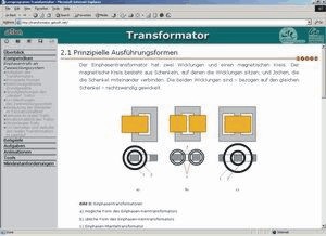
For further basic information we recommend the programme of the TU Ilmenau “Transformator”
|
|
 http://getsoft.net/trafo/index2.html http://getsoft.net/trafo/index2.html
|
|
Beginning with the electro magnetic basic laws (magneto motive force and induction laws) and the electric net equations of primary to secondary, the electric equivalent circuit diagram for a one-phase transformer is derived step by step. No-load and short-circuit test demonstrate how to determine all values of the equivalent circuit diagram. Real technical transformers show current ideal characteristics. Which parameters, diagrams and equations are needed to describe the characteristics is given. The focus is on the no-load characteristics by considering non-linear characteristic lines of the core material.
The chapter “tasks” gives parameters of technical transformers. On an example these parameters are used to calculate the elements of the complete equivalent circuit diagram.
|
|