|
|
|
Inrush current
The higher the induction in the transformer core the smaller the remaining air gap. And the higher the copper losses, the higher the inrush current. Guideline values for 230 V primary voltage:
Inrush current approximately 3 up to 5 ms:
|
|
Type size
|
Toroidal transformer
|
Bobbin transformer
|
|
up to 50 VA
|
6 A
|
5 A
|
|
up to 100 VA
|
15 A
|
7 A
|
|
up to 200 VA
|
30 A
|
20 A
|
|
up to 300 VA
|
60 A
|
30 A
|
|
up to 500 VA
|
130 A
|
45 A
|
|
up to 750 VA
|
250 A
|
55 A
|
|
up to 1000 VA
|
350 A
|
70 A
|
|
up to 1500 VA
|
450 A
|
-
|
|
up to 10000 VA
|
2000 A
|
500 A
|
|
|
|
|
Primary fuse
Small transformers can be fused with laggy safety fuses (sign T). For big transformers and toroidal transformers we recommend super laggy safety fuses (TT) on the primary side.
Selection of safety fuses with rated values conform to DIN 41662 IEC 127-2
|
|
32 mA
40 mA
50 mA
63 mA
80 mA
100 mA
125 mA
160 mA
200 mA
250 mA
315 mA
400 mA
500 mA
630 mA
700 mA
800 mA
|
1 A
1,25 A
1,4 A
1,6 A
2 A
2,5 A
3,15 A
4 A
5 A
6,3 A
8 A
|
10 A
12,5 A
16 A
20 A
25 A
35 A
50 A
63 A
80 A
100 A
|
|
|
|
|
NTC thermistors as current inrush limitators
NTC-resistors or so called Surge-Gurads can be used as well. The current is limited for 1 to 2 seconds. While in cold condition, means during the start-up of the transformer, NTC thermistors have a way higher resistance than during the warm condition and thus they can limit the current. After a short heating due to the inrush current the NTC becomes low-impedant and is able to deal with permanent currents up to 20 A. The selfwarmth reduces the resistance of the NTC to less than 10% of the cold resistance during the start-up. After a break of the power supply the NTC thermistor cools down to ambient temperature and increases the resistance again. A certain time of cooling is needed though until the NTC reaches his full safety function again. This can take up to two minutes, depending on disksize and ambient conditions. Before the end of the cooling time the NTCs are not able to redeem their full limiting functions. We choose the NTC depending on transformer characteristics. During the usual operation of the transformer, means the low-impedant condition of the NTC, it becomes very hot. Temperatures up to 200°C and more are possible. Here is a small selection:
|
|
Type
|
Current
|
max. temp.
|
R cold
|
R warm
|
Diameter
|
Thickness
|
|
9930031
|
1,3 A
|
220°C
|
200 Ohm
|
1,90 Ohm
|
15 mm
|
8 mm
|
|
9930032
|
2,0 A
|
220°C
|
40 Ohm
|
0,60 Ohm
|
15 mm
|
6 mm
|
|
9930033
|
3,0 A
|
220°C
|
120 Ohm
|
0,90 Ohm
|
20 mm
|
6 mm
|
|
9930034
|
4,0 A
|
270°C
|
12 Ohm
|
0,22 Ohm
|
12 mm
|
8 mm
|
|
9930035
|
6,0 A
|
270°C
|
10 Ohm
|
0,15 Ohm
|
15 mm
|
6 mm
|
|
|
|
|
TSR device
TSR, transformer switch relay (helps when current inrush limiters reach their limits)
The TSR is an electronic inrush current limiter which does not only limit the inrush current of transformers but avoids it completely. This makes it possible to quickly fuse transformers on their primary side with the rated current. A latency between the switches is not needed at all. A transformer or a parallel- or series circuit of transformers is pre-magnetised for 0,2 seconds by the TSR and then started without any inrush current. The TSR is short circuit proof if safeguarded properly with a 16 B fuse. A control input allows to switch via a SPS etc. Switch losses are avoided completely and also frequent switching is no problem. Even fast clocking with versions is possible. One or three-phase TSRs are available. Please send us an inquiry. (PDF-datasheet).
All table values are examples. Technical data can be changed by our suppliers.
|
|
|
Toroidal transformer and fast fusing
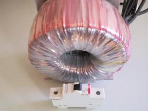
The picture shows a 1 kVA, 230 V toroidal transformer and a C 4 A circuit breaker. The toroidal transformer is constructed to have low losses and has a rated current of 4,3 A and an inrush current of about 56 times the rated current = 240 A.
The C 4 A circuit breaker reacts at 6 times the rated current = 24 A rather fast. The inrush current of the transformer is 10 times too high. Like this the transformer can’t be fused.
It’s too bad that those two don’t fit together without any problems, because each of them would have a lot of advantages. The low loss transformer is stress stiff, remains almost cold and has no-load current which can be ignored.
The C 4 A circuit breaker would be able to protect the transformer as well as the long connectors behind the transformer perfectly against overload or short-circuit. As a short-circuit can also occur at the end of a long conductor the appearing currents aren’t high yet the circuit breaker has to trigger. In plant engineering such long conductors to supply all those small actuators with 24 VAC are pretty common. Up to now one had to run cables with high cross sections which are used by transformers and a fusing of high rated currents. Thick cables cost a lot more than thin cables though.
If a so called transformer switch relay is set in between the two mentioned devices from above work together properly. Control transformers with low inrush current that were used until now and are common on the market can become very hot in the no-load condition already - so hot that one can’t touch them anymore. The reason of heating transformers lies in the construction. Transformers can either be designed for low losses or for low inrush current. Both at the same time doesn’t work. If one would design a transformer with low inrush current and also low on losses, the transformer would be way bigger and more expensive than a low loss transformer due to the way smaller induction B.
The transformer with low inrush currents satisfies superficially the requirements on price and technology and thus the troublesome heat development and the higher electricity consumption is accepted. Very often a cooling system is implemented. The alternative to a transformer getting hot in no-load already would be a low-loss transformer. The high inrush current would trigger the circuit breaker that fits to the rated current every time though.
Current inrush limiters help to limit the high inrush currents of low-loss transformers, but only in some cases. They usually contain a delayed bridged NTC or other fixed resistors or they only consist of NTCs. With this only the rare start-up after a long pause is controlled though. The start-up after a short-circuit can’t be handled at all by these current inrush limiters.
If many start-ups happen consecutively or if there are short interruptions of line voltage, the resistors in the current inrush limiters will be hot or still bridged and thus they won’t limit the inrush current or they’ll even get damaged.
So called transformer switch relays, which avoid the inrush current completely, allow it to use low-loss transformers and they fulfil all of the above mentioned requirements. The selection of the fuses is very easy.
The start-up with a transformer switch relay TSR, which turns on a low-loss 1 kVA toroidal transformer, can be seen on the picture below.
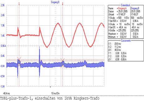 The transformer is unloaded at the start-up. With the TSR we get a no-load current of ca. 80 mA peak when starting. (Upper curve = U, lower curve = I) The transformer pre-magnetised for a short while by nonpolar voltage peaks before turning on fully in the perfect moment. The saturation of the core is avoided. The transformer is unloaded at the start-up. With the TSR we get a no-load current of ca. 80 mA peak when starting. (Upper curve = U, lower curve = I) The transformer pre-magnetised for a short while by nonpolar voltage peaks before turning on fully in the perfect moment. The saturation of the core is avoided.
For more than 7 years you find these current inrush avoiders on the market and they are used in more and more sensitive areas like medical devices. When under load you always have only the rated current, even in the start-up. Without load, as you see above, you have only the no-load current at the start-up. A TSR can switch the rated current more than 5 million times during its lifetime, even consecutively.
This makes it possible to use a circuit breaker that fits well to the transformer and can also fuse the partial load operation. See description further down. A PKZM0-2,5 would be a good example for the transformer with 1 kVA power at 400 V and 2,5 A rated current. A B or C type double switch below the rated current is also applicable, if quicker fusing is wanted. A secondary fuse can be ignored in this case.
Only toroidal transformers have such a small no-load current, that it doesn’t lead to a heating of the core at all.
For the future, this makes them very interesting as energy efficient transformers, that are very load stiff, as the only downside that they have can be undone with a TSR. This downside is the high inrush current.
If you want n especially stiff output voltage, you can also use a bigger transformer with the TSR. The higher no-load losses of around 7W more of a 2000 VA transformer instead a 1000 VA won’t matter at all then. The total losses are even smaller during the partial load. A 2 kVA transformer can be fused with 0,5 kVA, if the load isn’t higher.
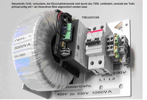
The following picture shows a low-loss control transformer, that is started with a TSR and quickly fused with a B or C circuit breaker at rated current.
 |
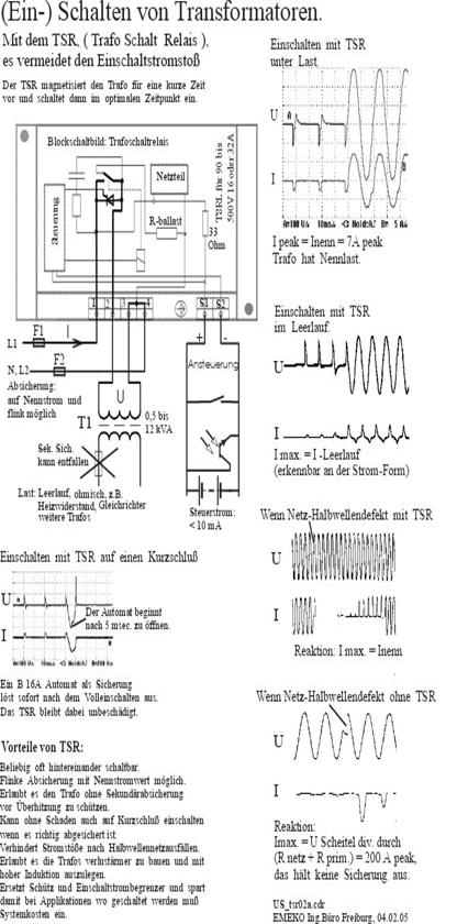
On the picture below you can see a block diagram of the TSR with a measurement curve of the start-up under load and no-load. Even when starting on a short circuit the TSR doesn’t get damaged if the fuses are done properly. After removing the short-circuit the TSR is ready for start-up instantly.
 |
|
|
|
What does it look like without a TSR?
|
|
|
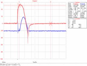 The picture shows the start-up of a low-loss 1 kVA transformer, which his fused with a PKZM0-4-T (no TSR running). The picture shows the start-up of a low-loss 1 kVA transformer, which his fused with a PKZM0-4-T (no TSR running).
Input A, above = voltage at transformer, Input B, below = current in transformer. The circuit breaker triggers within 10 ms after the starting.
This low-loss control transformer has an iron core with no airgap and low loss material. At 1 kVA it has an inrush current of 100 A peak, this are 140 Aeff at a 400 V primary winding. In total this is 56 times the rated current. Toroidal transformers of this size which are very low on losses even have an inrush current of more than 180 Aeff. This is 72 times the rated current.
There are no circuit breakers that have a higher short-circuit trigger current than 22 times rated current. They would turn off the so called soft short-circuits too late or not at all and this could lead to fire risk.
The selection of the fuse that fits to the transformer without a TSR is pretty tough, even for transformers with low inrush current. Shown in the following example.
One-phase control transformers are usually operated with 400 V, also between conductors in three-phase nets. At the output they generate mostly 230 VAC or 24 VAC. The primary fuse with two safety fuses is not allowed if they don’t trigger together. Most of the times motor circuit breakers are used as a transformer version.
For example, if a 1 kVA control transformer with low inrush current, primary 400 V and 2,5 A rated current without TSR is used, then you need to put a PKZM0-4-T with 4 A rated current in front of it, so that the inrush current, even though it’s low, doesn’t trigger the fuse. This special circuit breaker has a set, quick minimum trigger level of 84 Aeff (21 times 4 A).
This is higher than a normal motor circuit breaker PKZM0-4, this one only has 56 Aeff and would definitely trigger the 1 kVA transformer with low inrush current. The adjustable fuse area of this switch reaches from 2,5 - 4 A. To trigger at overload of the 4 A switch, the button for the thermal trigger level is turned back compeltely to 2,5 A, which is the lowest value. This value only just fits to the rated current of the 1 kVA transformer. However, with a PKZM0-2,5-T, which would fit to the rated current and also covers the partial load area, the inrush current triggers the circuit breaker, as this only has a minimum trigger level of 21 times 2,5 A = 52,5 Aeff.
Transformers with low inrush current have a inrush current around 15 - 25 times rated current according to the manufacturers, the real inrush current is usually higher though, as it’s only calculated, not measured. The transformer has to fit perfectly to the circuit breaker due to the always occurring inrush current. This requirement can only be met by control transformers with low inrush current and never by voltage stiff or low-loss transformers. Low-loss transformers have to be designed with a small inner resistance of the copper winding. The primary winding resistance limits together with other factors the inrush current. A high inner resistance leads to a small inrush current but increases the losses and vice versa.
|
|
|
Example of plant engineering
|
|
|
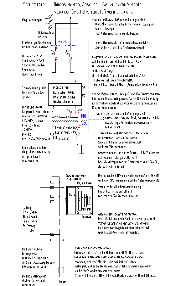 For the fusing of long output conductors as you find them in plant engineering one has to consider that a short-circuit at the end of the conductor has to trigger the fuse. The short-circuit current is low because of the high resistance of the long conductor. A high trigger level for the quick triggering of the circuit breaker is not enough anymore in this example. For the fusing of long output conductors as you find them in plant engineering one has to consider that a short-circuit at the end of the conductor has to trigger the fuse. The short-circuit current is low because of the high resistance of the long conductor. A high trigger level for the quick triggering of the circuit breaker is not enough anymore in this example.
Furthermore an additional rated current fuse that is adjustable and quick on the secondary side is necessary. To safely fuse soft short- circuits it is necessary, that the inner resistance of the transformer is pretty low, which allows a smaller cable cross section of the outgoing line. The sum of the resistance in a circuit defines the short-circuit current that has to trigger the fuse. The copper that was saved at the transformer, might be needed as a multiple for the lines behind the transformer. The application to the left shows how a energy efficient control transformer with 0,8 kVA with 400 V to 230 V is used in plant engineering to supply the widely spread consumers.
The two wire line behind the transformer is 440 m long and can only be put in 1,5 mm cross section for 230 VAC. A 24 VAC line on the secondary side, which often occurs in reality, this applies as well, only with higher cross sections.
The primary sided fuse has to be done with a B2A, which used to be unthinkable for such a transformer because of the low and quick triggering fusing. It protects the long cable on the secondary side from overload as well. The TSR always turns the low loss toroidal transformer on without inrush current and thus the B-type 2A circuit breaker doesn’t trigger. Like this the primary automaton can trigger in less than 5 seconds on the 440 m far secondary side. The short circuit current at primary is only 10 A high. See calculations at the example below. Secondary there’s only a max. of 17 A until the fuse triggers. Like this the 1,5 mm conductor is protected from fire at a short-circuit. Of course all loads that are on secondary may not have more than 4 A for a short while, otherwise the fuse triggers.
Without TSR and with fusing with a PKZM0-4-T on primary and with no further fuse on secondary, the 1,5 qmm line technically may not be longer than 50 m, because then the current that triggers the circuit breaker would not flow anymore. Longer lines need a bigger cross section. However the transformer still has to be low on inrush current so that the circuit breaker doesn’t trigger at the start-up. If the line has to be 440 m long, one can save 300,-€ on the input cable with the TSR. The TSR alone allows a 1,5 qmm cable, without TSR it has to be a 4 qmm cable. A 4 qmm cable costs around 350,-€ more than a 1,5 qmm cable. Without the TSR in front of the transformer and with an additional fuse on secondary (PKZM0-4, set to 3,4 A) that triggers after 5 seconds at 40 A in case of a short-circuit, the 440 m cable still needs 4 qmm cable and thus is 300,-€ more expensive than the version with TSR.
The problem with such applications is not the input and hard short-circuits, but the far away and soft short-circuits, which have to make the fuses trigger in worst case. A big 5 seconds triggering current leads to a big cross section and vice versa. Here it helps a lot when there is no inrush current and the fuse only has to be set to the requirements of the circuit breaker.
|
|
|