|
|
|
Datasheet as PDF
Toroidal chokes for application at higher frequencies up to 150 kHz
|
|
|
|
     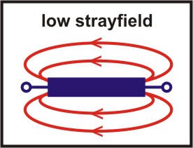 
|
|
|
Fields of application
|
|
|
In primary and secondary clocked switch mode power supplies, not controlled and unregulated power supplies with transformers, electronic ballast for fluorescent lamps, U-coverters, line-commutated converters (also classic I-converters), phase angle control dimmers and many more.
|
|
|
Description
|
|
|
PFC-chokes are one or two winding chokes with toroidal cores made of pressed soft magnetic powder material. The following materials are often used:
- MPP (79%-81% Ni, 17 % Fe, 2%-4% Mo)
- High Flux (50% Fe, 50% Ni)
- Cool My, Sendust (FeSi9,6 Al5,4)
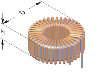
These cores are usable over a wide range of permeability and have a smaller Lo/Ln factor at lower permeabilites than at higher permeabilities. PFC toroidal chokes are storage chokes for the application in active power factor correction circuits. Lamination chokes e.g. EI types are used in passive PFC circuits in contrary. This enables power factors of devicesor systems with a cos φ ≈ 1. The chokes are conform to EN 61000-3-2. They are suitable for high frequencies up to 150 kHz. The toroidal core is the ideal geometric shape for the magnetic flux, this results in a low magnetic stray field and low losses. The winding is constructed for low voltages and is wound with low stray field. The dimensions are determined by the energy E = 0,5 L I².
|
|
|
Drawings and tables
|
|
|
open, lying version potted, lying version
|
|
 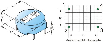
|
|
Type
|
Current
[A]
|
No-load
inductance
[µH]
|
Rated
inductance
[µH]
|
Energy
[mWs]
|
DC-resistance
mOhm
|
Dimensions
|
Copper
weight
[g]
|
Total
weight
[g]
|
|
open version
|
version with housing
|
Num.
pins
|
f1
|
f2
|
f3
|
|
D
|
H
|
L
|
B
|
H
|
|
DR...4
|
1,00
|
5000
|
2200
|
1,1
|
725
|
28,0
|
13,0
|
32,6
|
33,2
|
19,2
|
4
|
30,0
|
20,0
|
5,0
|
17
|
45
|
|
DR...4
|
1,60
|
5000
|
2000
|
2,6
|
520
|
38,0
|
16,0
|
41,7
|
42,5
|
24,3
|
4
|
40,0
|
15,0
|
5,0
|
30
|
95
|
|
DR...4
|
2,00
|
2500
|
1200
|
2,4
|
265
|
37,0
|
15,0
|
41,7
|
42,5
|
24,3
|
4
|
40,0
|
14,0
|
5,0
|
41
|
115
|
|
DR...4
|
2,50
|
1000
|
550
|
1,7
|
140
|
31,0
|
16,0
|
41,7
|
42,5
|
24,3
|
4
|
40,0
|
14,0
|
5,0
|
17
|
65
|
|
DR...4
|
4,00
|
500
|
280
|
2,2
|
65
|
39,0
|
16,0
|
41,7
|
42,5
|
24,3
|
4
|
40,0
|
14,0
|
5,0
|
39
|
110
|
|
DR...4
|
6,30
|
130
|
80
|
1,6
|
17
|
31,0
|
15,0
|
32,6
|
33,2
|
19,2
|
4
|
30,0
|
14,0
|
5,0
|
17
|
65
|
|
DR...4
|
8,00
|
125
|
60
|
1,9
|
14
|
31,0
|
15,0
|
32,6
|
33,2
|
19,2
|
4
|
30,0
|
14,0
|
5,0
|
19
|
67
|
|
Technical changes and optimisation reserved. All details are guide values, variations are possible.
|
03/2012
|
|
|
|
|
|
open, upright version potted, upright version
|
|
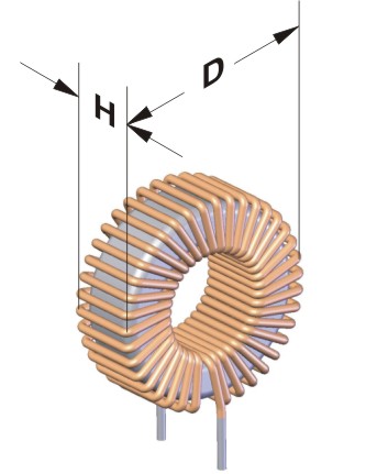 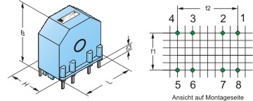
|
|
Type
|
Current
[A]
|
No-load
inductance
[µH]
|
Rated
inductance
[µH]
|
Energy
[mWs]
|
DC-resistance
mOhm
|
Dimensions
|
Copper
weight
[g]
|
Total
weight
[g]
|
|
open version
|
version with housing
|
Num.
pins
|
f1
|
f2
|
f3
|
|
D
|
H
|
L
|
B
|
H
|
|
DR...4
|
1,00
|
5000
|
2200
|
1,1
|
725
|
28,0
|
13,0
|
32,0
|
35,0
|
20,5
|
4
|
17,5
|
27,5
|
5,0
|
17
|
45
|
|
DR...4
|
1,60
|
5000
|
2000
|
2,6
|
520
|
38,0
|
16,0
|
43,0
|
47,5
|
28,0
|
4
|
25,0
|
40,0
|
5,0
|
30
|
95
|
|
DR...4
|
2,00
|
2500
|
1200
|
2,4
|
265
|
37,0
|
15,0
|
43,0
|
47,5
|
28,0
|
4
|
25,0
|
40,0
|
5,0
|
41
|
115
|
|
DR...4
|
2,50
|
1000
|
550
|
1,7
|
140
|
31,0
|
16,0
|
37,0
|
40,0
|
25,5
|
4
|
22,5
|
30,0
|
5,0
|
17
|
65
|
|
DR...4
|
4,00
|
500
|
280
|
2,2
|
65
|
39,0
|
16,0
|
43,0
|
47,5
|
28,0
|
4
|
25,0
|
40,0
|
5,0
|
39
|
110
|
|
DR...4
|
6,30
|
130
|
80
|
1,6
|
17
|
31,0
|
15,0
|
37,0
|
40,0
|
25,5
|
4
|
22,5
|
30,0
|
5,0
|
17
|
65
|
|
DR...4
|
8,00
|
125
|
60
|
1,9
|
14
|
31,0
|
15,0
|
37,0
|
40,0
|
25,5
|
4
|
22,5
|
30,0
|
5,0
|
19
|
67
|
|
Technical changes and optimisation reserved. All details are guide values, variations are possible.
|
03/2012
|
|
|
|
|